9 minute read
AIS Managed Firewall
Synopsis: How to unbox, set up, configure (multiple ways) and test
WAN is interface 1, with dhcp as default and LAN is interface 2, 192.168.1.1 as default. Plug PC into port2, plug port 1 into upstream to start to configure. This example assumes you are at home or the office (you should have an initial internet connection to get a couple of packages)
User: admin Pass:
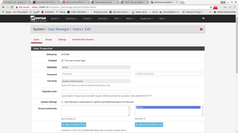
Change password (Go into System gt User Manager gt Users)

Then Edit the admin user

Your browser should redirect you to port 444, so you stay in the firewall, but this has been hit or miss in my experience. If your browser doesn’t redirect you within 10 seconds, change your URL bar to https://192.168.1.1:444
Change firewall rules to allow all access to this firewall on LAN.
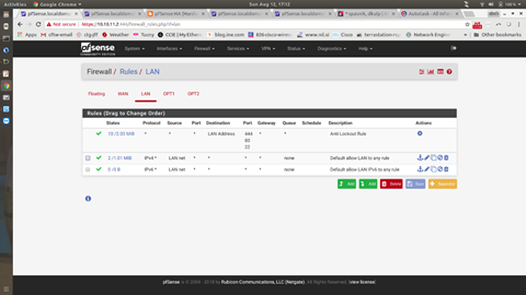
Your page should end up looking like the above picture. **Notice** how there are no IP’s in this picture.
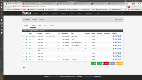
The example above has a line from a test network (10.111.111.0/24), that is not needed. Everything else should look the same. Again, **Notice** how there are no IP’s in this picture.
Install any needed packages: For any AIS MFW running Soft Ether (Go into System gt Package Manager gt Available Packages and select Shellcmd). This will install, very quickly, and your screen should look like the below when done.

Your LAN/WAN should already be assigned. The WAN can stay until the last few changes. The LAN should be changed to the IP scheme you will be using. If you are deploying a firewall pair (the next part does NOT apply to single firewalls and is not needed if this is a single firewall deployment) you will need an interface on each firewall assigned as a PFSYNC interface. We are going to use the firewall’s 4th interface for this. The software uses 0-3 in PFSense, so to us, it looks like interface 1, 2, 3 and 4. In PFSense, it is 0, 1, 2 and 3). (Go into Interfaces gt Assignments)

The above picture is what it will look like on the Soft Ether side when you are done (again, if you are not doing a firewall failover pair, this picture is not for you). For me, this was not the most intuitive screen. This is just adding interfaces. WAN is 0, LAN is 1, we are going to choose 3 from the Available network ports dropdown (there will only be 2 and 3 available to us). Click on Save and then OPT1 will show up in the Interface Assignment menu.
Click on OPT1 and you will have values to fill in like the screen below

The screen above has an address of 172.16.254.2/30. This address should be something that is not on the network anywhere else. This is a totally private network (the other side would be 172.16.254.1/30) and it only used to have the 2 firewalls talk to each other. Make sure to tick “Enable Interface” and make sure to Save at the bottom.
Firewall rules for the above interface (and later for GRE interfaces) should be a single line, permitting everything

Still working with a firewall pair, your virtual IP is customarily a .1 ,with your firewalls being .2 and .3. (Go into Firewall gt Virtual IP’s)

The above picture is what it will look like when you are done. The below picture is how you get there:

The above screen has the CARP radio button ticked. Single Address should already be chosen. Use your new IP address you will use (if your firewall pair is using .2 and .3, this will be .1.. For example, the customer has an existing network of 10.111.111.0/24. Their current firewall is 10.111.111.1. We are installing two new firewalls at .2 and .3.. But their virtual IP to share between them will be 10.111.111.1/24). For the VHID password, use a secure password. For the VHID group, leave it at 1. **IMPORTANT** The firewall you choose to be the primary should click SAVE. The secondary should change the “Advertising Frequency” to “2”. This makes the primary have a lower value.. And that is how you set which one is the master.
You will make these same changes to the Secondary firewall.. Same screen.. Same passwords.. Just that last value is different.
Once you have that done, you should check the status (Go into Status gt CARP (failover)

The above is a picture of the Secondary firewall.
At this point, you should have both firewalls up and configured for failover with all the correct rules in place to test the failover. Ping the new virtual IP and pull the Interface 2 cable from the Primary firewall. You should lose a couple of pings and then it should resume. If this does not happen, you have to stop and figure out why.
GRE
The following instructions are if you are using a firewall with a GRE tunnel. The process above specifies interface 1 is for WAN, 2 is for LAN and if we are using a pair of firewalls, 4 is for PFSYNC. We don’t need another physical interface for GRE. GRE stands for Generic Routing Encapsulation. It is a software interface. GRE should be used in scenarios where there is a need for dynamic routing (such as OSPF). An IPSec tunnel can’t carry OSPF (or EIGRP, or RIP), but a GRE tunnel can.
You assign a GRE tunnel to a real Interface by going to Interfaces gt Assignments. One of the options is GRE.

Click on GREs and it will be blank. Click on Add and the following screen is what a finished product looks like

This is one of the more complicated things in Networking. So don’t feel like you “don’t get it”, this isn’t easy. The Parent interface should almost always be WAN. The remote address is the address of the Public IP of the router you are talking to. The GRE tunnel local address is the new GRE network we are going to use. Nobody will ever see these address, as they are software and are just being used as a transport. I always use 10.128.1.X/24 as my GRE network. The GRE tunnel remote address is another 10.128.1.X/24 address on that Public IP you are talking to. You need to plan this out before jumping into this page. You should know:
1. The public IP of the router you are going to create your tunnel to partner
2. The subnet you are going to use for your GRE network
OSPF
For failover solutions, we want the firewall to know the primary path dynamically. When the firewall can’t hear about the primary path, we will help and have another route. The failover we have shown so far talks about the hardware aspect... if the firewall dies, the other firewall knows about it and takes over. An earlier section had you install FRR. Now we will configure it. We are only going to run OSPF on the primary firewall. The secondary will run Soft Ether tunnels. (Go into Services gt FRR Global/Zebra)

Tick the Enable button. For the Master password, use a secure password. Leave the CARP status at None and make the Router ID the inside interface of the firewall. Click Save and then go back to the top and click on OSPF (see picture above).
Now you are in the OSPF Settings (you can also get to this screen by going to Services gt FRR/OSPF)
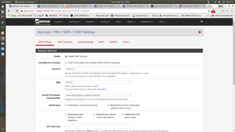
Tick the Enable OSPF Routing box. Set your Router ID to the same IP you used in the previous step. Set the AREA to “0.0.0.0” and go to the bottom and hit Save.
Click on OSPF Interfaces (I saw some odd behavior here that I can’t reproduce. You can’t enable OSPF routing until you have OSPF interfaces, so make sure you save everything). The picture below shows adding interfaces. You must enable the LAN interface in all cases. If this is your primary interface, your GRE tunnel interface will be called OPT1. This will also need to have OSPF running on it.
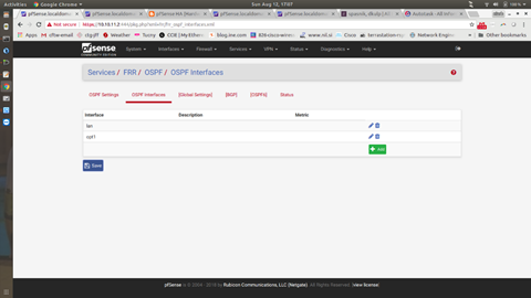
The below picture shows the setting for LAN

The next picture shows the OSPF Interface settings for OPT1 (notice they are the same as LAN)
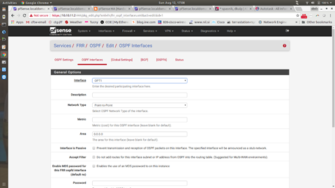
The Network Type for both is very important (it has to do with what kind of route OSPF advertises), so make sure to choose Point-to-Point. If you would like to know more about this, come see me.
All of this will only be done on routers that are primary in a single ISP situation. If there are two ISP’s, then it needs to be done on both routers (Router ID is unique, this can’t be the same, which is why I suggest putting the Router ID as the LAN interface IP).
The last step is a difficult one to put into pictures. You can use Google to search the term “floating static route”. The PFSense unit does not natively understand this. The FRR tool does, so we have to make a manual entry. (Go to Services gt FRR Global/Zerbra and click on Raw Config)

This adds a route to the routing table of the PFSense device with a weight. The route we learn from OSPF will go away if the ISP drops and this route will take over. We point this route at the Soft Ether Layer 3 gateway.
TESTING
You should have already pulled the LAN cable on the primary firewall to test that your hardware failover is working. For testing the GRE/OSPF/Floating Static/Soft Ether test (yes, this next cable pull will test all of those), you will need to have the remote side set up as well. By pulling the remote primary WAN cable, you will be:
1. Making the OSPF neighbor fail
2. Making the route to the remote side disappear
3. Making the floating static come to life
4. Make the route use the Soft Ether tunnel